
Coefficient of Lift


                                                                  Lift Coefficient:

Coefficient of lift CL is defined as the lifting ability of the wing which depends on geometry of the airfoil. Coefficient of Lift Changes with change in angle of attack and it differs for symmetric and Assymetric airfoils.

To Know about Coefficient of lift CL we plot the variation of lift with change in angle of attack.


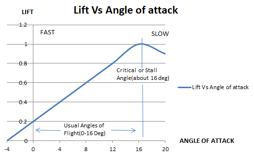
For asymmetric airfoil at 0 degree of angle of attack the lift generated is minimum and at 15-16 degrees its maximum which is called CL max. Angle of attack remains a straight line between 0 -12 Degrees. Above 12 Degrees rate of increase in lift reduces and forms a peak. The Peak formed denotes the maximum Angle Of attack CL max. At angles of attack beyond this point Coefficient of lift CL decreases which tends to reduce the lift.

 Now the Airfoil is stalled and it cannot produce further lift to maintain steady straight and levelled flight. The Angle at which CL max occurs is called stalling angle of attack of the Airfoil.

The normal range of the Airfoil is between 0 Deg angle of attack and stalling angle of attack.

For symmetric airfoils at 0 degrees of angle of attack there is no lift. Each airfoils possess its own lifting Characteristics, so it’s possible to compare Assymetrical and Symmetrical Airfoils.


Assymetrical Airfoils generate lift at low angle of attacks and produce stall at low angle of attacks than a symmetrical Airfoil.


Comments

Post a Comment

Popular posts from this blog

AIRFOIL TERMINOLOGY

                       Air foil Terminology What is an airfoil? How an air foil is described in modern science, what are the parameters that determines its shape? An Air foil is primary building block of an aircraft which has two edges namely leading edge and trailing edge, the straight line connecting the leading and trailing edge of the air foil is called as chord line. The line which is drawn equidistant from the upper and lower surfaces of the air foil and connecting the leading and trailing edge is called as mean camber line.The distance between the leading and trailing edge is called chord of an air foil.   The maximum distance between the mean camber line and chord line is referred as maximum camber. This is one of the variables that determine the aerodynamic characteristics of the wings. Maximum thickness to chord ratio is expressed in terms of percentage. For subsonic wings the ratio is normally 12-14%   Depending on the camber (curvature) of the air foil it is d

Form Drag

                                                                       Form Drag Form drag is experienced in the surface of the aircraft when the streamlined airflow separates and becomes turbulent. To experiment form drag keep a flat plate on the streamlined airflow, now the pressure before the plate is atmospheric and the pressure after it is below the atmospheric which results in sucking effect behind the plate and vortices are formed. It is mandatory to delay the separation point of airflow and this is achieved by altering the shape or streamline of the given object. When the airflow changes its direction rapidly form drag experienced is higher. A fairing is fitted around the fixed undercarriage leg to reduce form drag to considerable extent. The resultant form drag depends on the length and maximum thickness of the streamlined object. The ratio of length to maximum thickness is called the fitness ratio. Fitness ratio = a/b At subsonic speeds fitness ratio of streamlined shapes is

AERODYNAMIC CENTRE

          AERODYNAMIC CENTER IN ASYMMETRICAL AIRFOILS THE CENTER OF PRESSURE MOVES ALONG THE CHORD LINE WITH CHANGES IN ANGLE OF ATTACK. AS THE ANGLE OF ATTACK INCREASES THE CENTER OF PRESSURE MOVES TOWARDS THE LEADING EDGE AND WHEN IT DECREASES IT MOVES TOWARDS THE TRAILING EDGE. A NOSE DOWN PITCHING MOMENT IS ALWAYS PRESENT AND INCREASES IN INTENSITY WITH INCREASING ANGLES OF ATTACK. HOWEVER THERE IS A POINT ON THE CHORD LINE ABOUT WHICH THE PITCHING MOMENT REMAINS CONSTANT,REGARDLESS OF ANY CHANGE IN ANGLE OF ATTACK. THIS POINT IS CALLED AERODYNAMIC CENTER. IN SUBSONIC AIRFLOW IT IS LOCATED AT A DISTANCE 25% FROM LEADING EDGE ON THE CHORD LINE. HOWEVER IN SUPERSONIC AIRFLOW IT IS CONSIDERED TO BE LOCATED ON 50 % FROM LEADING EDGE ON THE CHORD LINE. FOR DESIGN PURPOSES IT IS CONSIDERED TO BE OVERALL LIFT FORCE TO ACT ON THAT POINT COMBINED WITH A PITCHING MOMENT OF CONSTANT STRENGTH.